
Shrink Sleeve Artwork Pre-Distortion for Bottle Contour
How shrink sleeve artwork is stretched before printing so it reads right once it grips the bottle — the prepress data flow, TD/MD role, and shrink proofing.
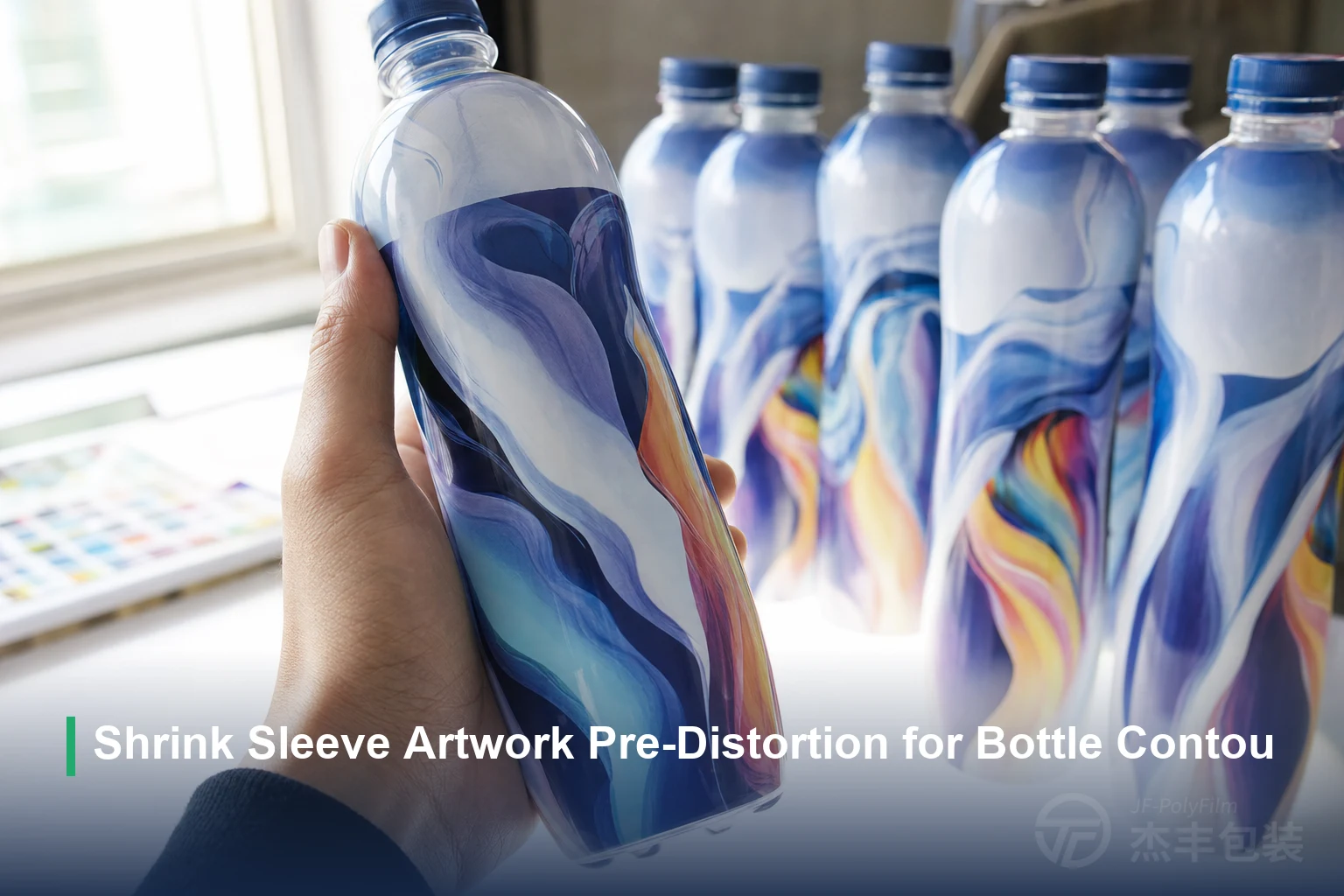
Shrink sleeve artwork pre-distortion is the prepress step that stretches a flat-film design in reverse — by the amount each part of the bottle will pull in — so the image snaps back to correct proportions once the sleeve grips the container. The file that looks distorted on-screen is the one that reads right on the shelf.
JFPolyFilm’s clear PETG shrink film prints direct in three shrink rates with a COA per batch, so the map is built on measured, repeatable figures rather than assumed ones.
Why shrink sleeve artwork must be pre-distorted
The core reason is a dimensional mismatch: the graphic is printed flat but has to read on a curved, tapered, three-dimensional bottle.
The design is deliberately deformed in the opposite direction to the shrink, so that the contraction pulls it back into the intended shape instead of away from it. Getting that reverse-map right is a prepress discipline; how the compensated file is then physically printed — gravure, flexographic, or digital — is a separate decision covered in PET shrink sleeve printing methods.
Where distortion comes from: the bottle contour
A cylinder of constant diameter would barely distort at all; a contour bottle distorts most at its sharpest curves and transitions.
| Bottle zone | Distortion risk | Prepress countermeasure |
|---|---|---|
| Shoulder / taper | High — fast diameter change squeezes graphics vertically | Add the most reverse-stretch here; keep small type and fine images off it |
| Waist / curve transition | High — the film pulls in sharply, waving straight lines | Map the local shrink precisely; favor abstract shapes over rigid rules |
| Neck | High — smallest diameter, largest draw | Avoid critical copy; let background carry the zone |
| Grip / handle recess | High — compound curvature in two directions | Keep logos and codes clear of it; test-fit before committing |
| Seam overlap | Moderate — double film thickness, alignment tolerance | No small type or continuous pattern across the seam |
| Straight body panel | Low — near-uniform diameter, little movement | Place barcode, key copy, and registration-critical art here |
How TD and MD shrink decide the direction of compensation
The compensation runs mostly in one direction because the film shrinks mostly in one direction. Pre-distortion is therefore overwhelmingly a circumferential stretch: the design is lengthened around the tube by the local TD figure at each height, with only a small vertical correction.
How much TD the container actually needs depends on its curvature, which is the separate question of choosing a shrink rate of 65, 75, or 80%.
Building the distortion map: from bottle profile to pre-distorted grid
The map is built from measured shrink, not estimated from the bottle drawing. The reliable route is a grid test: a regular pattern of squares is printed on the actual production film, sleeved onto the real container, and run through the shrink tunnel at the target temperature.
Proofing: grid sleeves, short runs, and COA cross-check
No pre-distortion is trusted until it is proven on the real container, so the map is validated by a physical shrink trial before any volume runs.
Where a proof still shows shrink faults — wrinkling, flagging, or uneven draw from the tunnel side rather than the artwork side — those are process problems addressed in solving PETG shrink film problems.
Frequently Asked Questions
What is pre-distortion in shrink sleeve artwork?
Why does shrink sleeve artwork distort on a bottle?
How is a shrink sleeve distortion grid made?
Related Articles
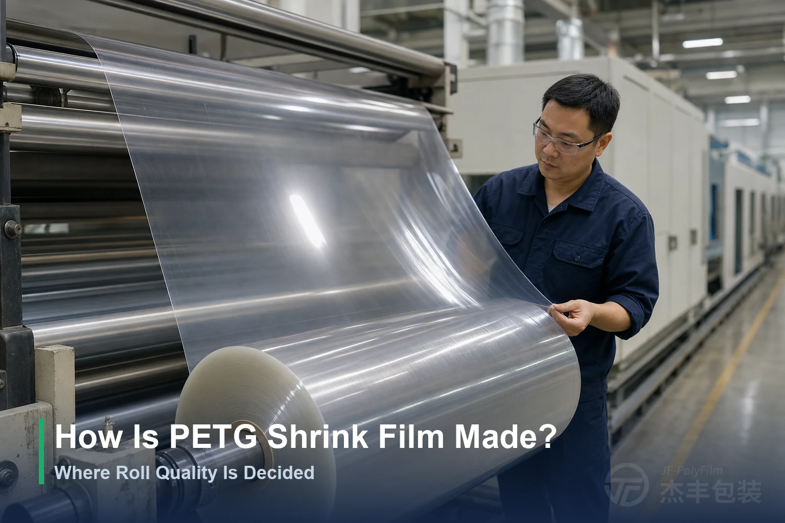
How Is PETG Shrink Film Made? Where Roll Quality Is Decided
How PETG shrink film is made, and which production stage sets each line buyers check on arrival: gauge tolerance, TD/MD shrink, haze, tensile strength, roll labels.
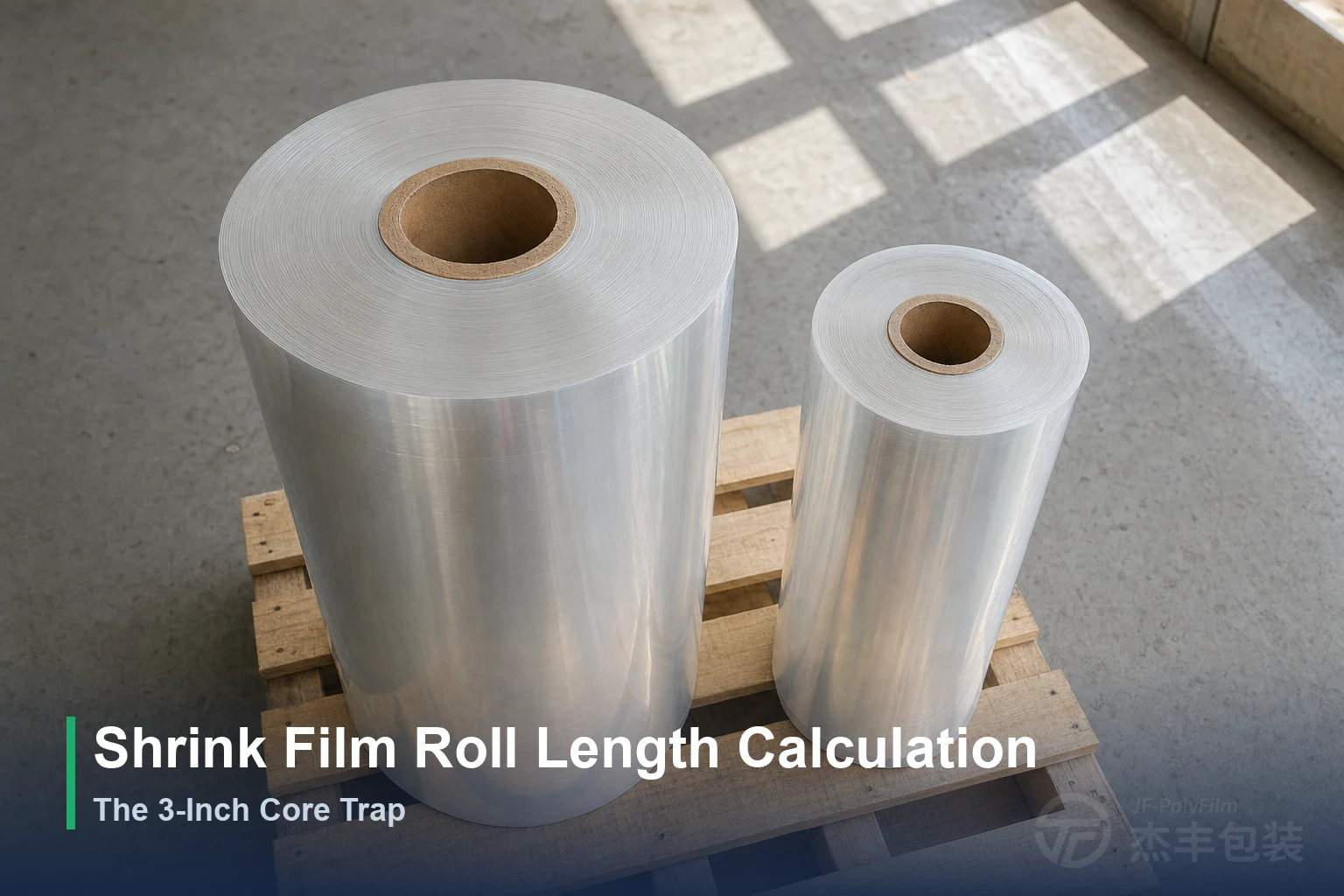
Shrink Film Roll Length Calculation: The 3-Inch Core Trap
Formulas linking roll diameter, length and weight, worked metric and imperial examples, a 30–60 μm diameter table, and why core size and trapped air shift the result.
Need Expert Advice on Shrink Film?
Our technical team can help you choose the right film for your application.
Contact Us